Understanding The Western Electric Double Coil Coin Relay. By Stan Schreier
Hello payphone pholks (and you other types of people).
A few members have asked me what the purpose of the permanent magnet is in a double coil coin relay. After trying to explain it by scribbling on table napkins, I realized that an article describing the operation of the double coil coin relay would be of value (to at least 3 people).
There are two basic laws of physics that the design of the relay was based upon (we wont count gravity).
1- Similar magnetic fields repel. 2- Opposite magnetic fields attract.
The Double Coil Coin Relay.
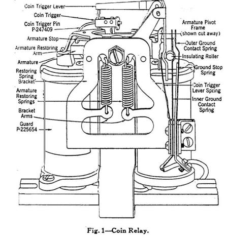
Fig.1 is a line drawing of an early (circa 1920) double coil coin relay. Youve probably seen it before. Its been used in countless Bell System publications.
The purpose of the coin relay is to direct the coins in the hopper of a 3 slot payphone to the coin return chute or the coin vault. This is done by the movement of a mechanical arm that is attached to the pivoting armature of the relay. The double coil coin relay is a polarized type relay. A polarized relay is a device that performs different mechanical functions, depending on the direction of current flow or the polarity of the voltage applied to it.
For the sake of simplicity, I will only show the armature, the permanent magnet, the two coils (electromagnets) and the polarity of the voltage applied to them.
The Permanent Magnet.
Over the years there were changes made to the shape of the permanent magnet.
Regardless of the shape, THE TOP IS ALWAYS THE (S) SOUTH POLE OF THE MAGNET!!!!!
The Coils.
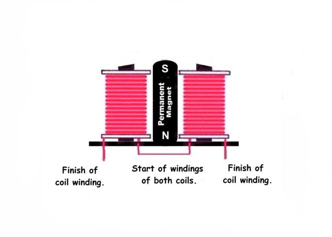
The two coils of a prepay, double coil, coin relay, are identical. They both have a resistance of 510 ohms. Although they are wired in series, they are out of phase. Meaning, the startof the windings of both coils are connected together and the applied voltage is connected to the finish of the windings of each. The start of the winding is the end closest to the core (center) of the coil. The finish is the outer most winding. Take a look at Fig.3.
Fig.3
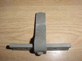
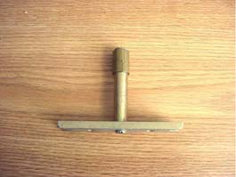
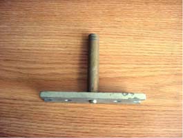
The Armature.
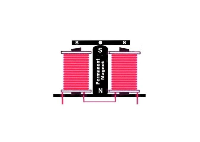
The armature is a component part of the coin relay that serves two functions. It pivots left and right to move the operating arm that controls the direction of coin flow out of the hopper. It is also a horizontal extension of the (S) south pole of the permanent magnet, since its mounted within the magnets field and made of ferrous material. Fig. 4 shows the armature in the ready position.
Fig.4
Triggered Position.
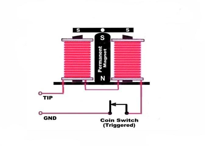
Fig.5 puts these parts together. A coin trigger switch has also been added. The coin trigger switch is a device that is hit by the coin on its travel down the coin track and into the hopper, during initial deposit. Its mounted on the right side of the frame of the coin relay. Scroll up to the line drawing to get an idea of the mechanics. When the coin hits the trigger, the switch contacts are closed. This connects the coin relay to Gnd. The other side of the coin relay is permanently connected to the Tip of the phone line.
The relay has three positions and four conditions.
*Note: these descriptions are for calls with no operator assistance.
1- Ready. The phone is on hook and waiting for the next call. 2- Triggered. The phone is off hook and an initial deposit has been made. 3- Refund. * The phone is on hook and the money is being refunded. 4- Collect. * The phone is on hook and the money is being collected.
Fig. 5 shows the coin relay in the Triggered position. The phone is in use and money is sitting in the hopper. Fig.5
COIN REFUND.
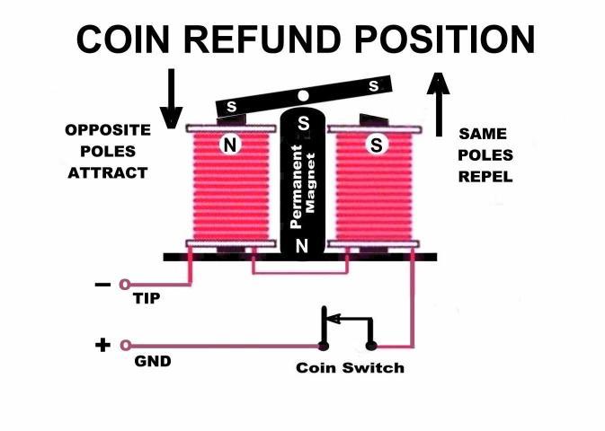
In the refund position a negative -110 volts has been applied to the Tip of the phone line with respect to Gnd. Since the Coin Trigger Switch is in the closed position, the 110 volts is across the coils of the coin relay. With the negative voltage on the Tip, the top of the left electromagnet is N (north). Since the coil windings are connected in series (but out of phase), the top of the right hand electromagnet will always be the opposite polarity, in this case S (south). Since the left hand electromagnet is N and THE ARMATURE IS ALWAYS S (south), the armature will be attracted to the left.
Remember . OPPOSITE MAGNETIC FIELDS ATTRACT!
Now, look at the right hand electromagnet. The polarity of that is S, the same as the armature. That will cause the armature to be repelled.
Remember . SIMILAR MAGNETIC FIELDS REPEL! . With the armature pivoted to the left, the attached operating arm (not shown), will swing to the right and direct the money sitting in the hopper to fall into the coin return chute. Fig.6
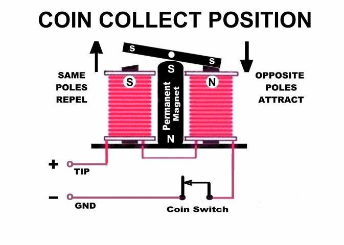
COIN COLLECT
In the Coin Collect position a positive +110 volts is applied to the Tip side of the line. Once again, the Coin Trigger Switch is closed, so the +110 volts is across the coils of the coin relay. With the positive voltage on the Tip, the top of the left hand electromagnet is S (south). Since the coil windings are out of phase, the top of the right hand electromagnet is N (north). Since the left hand electromagnet is S and THE ARMATURE IS ALWAYS S (south), the armature will be repelled.
Remember . SIMILAR MAGNETIC FIELDS REPEL!
Now, look at the right hand electromagnet. The polarity of that is N, the opposite of the armature. That will cause the armature to be attracted.
Remember . OPPOSITE MAGNETIC FIELDS ATTRACT!
With the armature pivoted to the right, the attached operating arm (not shown), will swing to the left and direct the money sitting in the hopper to fall into the coin vault.
Fig.7 And Then?
After the coin relay has either returned or collected the contents of the hopper, it returns to the ready position. The Coin Trigger Switch opens removing the voltage (regardless of polarity) from the GND side of the coils.
What amazes me is the fact that this device was used in the Western 7A coin collector, years before the Gray/Western 3 slot 50A was developed. That means the design survived well over 60 years virtually unchanged.
Getting back to the reason for the permanent magnet. Without it the armature wouldnt know which way to pivot. Its the fixed condition that a device with variables works against. PS
The single coil relay that came many years later also had a permanent magnet. Its hidden but its there. I wonder how many of you know where?
30
Stan Schreier
|
|||||||